Saturday, October 10, 2009

Privatization of utility tunnel

I want some case studies about privatization of utility tunnel's construction and maintenance.
If you have any information that explain the approaches of privatization please send it to me.

Sunday, September 20, 2009

Singapore high voltage cable tunnels

Large diameter tunnels for high voltage power circuits

Nearly 30km of large diameter tunnels ranging in diameter from 3.5m to 6m have been designed to carry high voltage power cables in Singapore for PowerGrid. Of these, approximately 6km are currently under construction. The 200 million Singapore dollar project began when PowerGrid commissioned Mott MacDonald, in association with Development Resources, to undertake a study into the feasibility of constructing large diameter tunnels to accommodate HV power cables.


Partition walls being errected in Gambas shaft

The initial scope of the study addressed the feasibility and implications of installing high voltage cables in tunnels, plus the design of two tunnels between Senoko power station and Gambas Avenue in the north of Singapore and between the sub-stations at Ayer Rajah in the west and Paya Lebar in the east. The study also developed route options and planning procedures for constructing an island-wide network of cable tunnels.

The Senoko to Gambas Avenue tunnel comprises 1.7km of twin 3.5m diameter tunnels accommodating ten power circuits. This contract includes the construction of four deep shafts. The Ayer Rajah to Paya Lebar tunnel totals 17km in length and measures 6m in diameter, also housing ten power circuits. The design includes ten shafts, with a maximum depth of 55m for general construction purposes plus cable entry and the permanent ventilation of the tunnels.

The feasibility of a third tunnel between Seraya and Labrador Sub-station, along the west coast of the island was also included in the study. The 8.5km route (4km of undersea tunnel and 4.5km of land tunnel) examined new bored and immersed tunnel solutions and the refurbishment of the existing undersea cable tunnel. Preliminary engineering was undertaken and tender documentation prepared to enable design-and-build contracts to be sought.

Fundamental to the design are the cooling requirements for the power circuits, the overall ventilation of the tunnels and space for installation of the circuits, safe working, maintenance and jointing. The tunnels and control buildings are equipped with fire and life safety facilities designed and specified by Mott MacDonald specialists.

Our commission on the project included the management of the overall tender process and went on to involve construction supervision. Completion of the Gambas Avenue and Labrador tunnels is scheduled for 2005.


TBM assembly in Gambas shaft


Gripper shield front


Errection of cutter head in Gambas shaft


Completed east tunnel of Senako Gambas project

source:
http://www.tunnels.mottmac.com/projects/?mode=type&id=3317

Wednesday, September 9, 2009

New utility tunnel for Africa’s busiest harbour

Durban Harbour is the busiest container port and harbour in Africa, and approximately 5000 ships visit it each year. As part of the approximately £80 million harbour expansion, a new 4.5m diameter, 500m long tunnel to carry services under the harbour, will replace an existing immersed tube tunnel when the harbour is widened and deepened in 2006.


Northerly view across entrance of the harbour, along the line of existing tunnel

Dredging works for the harbour expansion will cut through the existing tunnel. This means that the new, longer and deeper tunnel needs to be in place and fully fitted-out before the harbour expansion can begin – resulting in a tight design and construction schedule.

Mott MacDonald was part of the team that won the design competition for the type of tunnel that should be constructed, and was awarded the contract to develop the tunnel for Durban’s eThekwini Municipality Water and Sanitation. The competition involved both the new utility tunnel and a 'people mover' tunnel, which would ferry people across the harbour to help in promoting tourism. However, this second tunnel was omitted from the construction contract.

Working with South African engineers, Goba, our design role involved providing technical assistance on the various tunneling options as well as advice on the people mover options and soft ground tunneling. South Africa has strong experience and knowledge in hard ground tunneling, but not as much practice in soft ground tunneling. The ground conditions encountered included river deposits and sandy clay which suited the use of a slurry tunneling machine, which had not previously been used in southern Africa.

Construction work on the tunnel commenced in mid 2005. Of particular note was the steep 20%gradients on each side of the crossing, and the use of a purpose-built vehicle to deliver the tunnel segments. Mott MacDonald had a permanent presence on the site during construction. Although the start-up of the tunneling works proved difficult, the works were completed only slightly behind schedule in August 2006.


Exisiting tunnel landfall structure on the southern side of the harbour entrance


Delivery of the Tunnel Boring Machine


Segments are stored ready for use


TBM being lowered into shaft


The TBM is prepared for launch.


Purpose-built vehicle for segment delivery


Test ring of tunnel segments

source:
http://www.tunnels.mottmac.com/projects/?mode=type&id=9568

Saturday, September 5, 2009

US Perspective: Challenges of Underground Facilities in Urban Areas

written by:

A.E. Elioff, Senior Professional Associate Project Management, Tunnel Engineering, PB Americas, Inc. and
C. Laughton, Project Manager for Underground Design and
Construction at Fermi National Accelerator Laboratory


The presentation will illustrate challenges to underground construction (in the USA, urban areas) using illustrations from both successful and unsuccessful underground projects – and the impact of these on current and planned underground construction. Projects are expected to include CSO/Water tunnels, NUMI and DUESL Projects,
WAMATA extension, (Virginia) Alaska Way Viaduct - Seattle, Los Angeles Metro System and Central Artery in Boston.

Paper

US Perspective: Challenges of Underground Facilities in Urban Areas

Presentation

US Perspective: Challenges of Underground Facilities in Urban Areas


Tuesday, August 25, 2009

Trenchless technology

Definition: Trenchless technology, as the name implies, stands for subsurface construction works where less trenches or no continuous trenches are required to be dug. It is a rapidly growing sector of the construction and civil engineering industry. It can be defined as "A family of methods, materials, and equipment capable of being used for the installation of new or replacement or rehabilitation of existing underground infrastructure with minimal disruption to surface traffic, business, and other activities.

Trenchless technology, often referred to as "no dig", is a rapidly growing engineering industry that eliminates the need for surface excavation. Trenchless technology is also used to minimize environmental damage and to reduce the costs associated with underground work. In other words, trenchless technology provides cost-effective sewer asset management. It involves pipe and sewer inspection, rehabilitation, and cleaning services.

"No dig" is exactly what it sounds like. There is no digging up of roads to replace gas and water pipes. When there is a need for pipe rehabilitation in the middle of a busy intersection, trenchless technology allows you to repair the pipe without having to dig up the entire road. Not only does this eliminate traffic problems, but it saves money because you do not need to repair the road that you would normally have dug up.

One of the most recent developments in trenchless technology is the use of robotics. One of the core benefits of using robotics is the measurable data it provides that allows agencies to better understand the state of their current systems. Robots are also able to enter hazardous environments that are too dangerous for people to access.

Wednesday, August 19, 2009

Prague's utility tunnels

Otakar Capek says the utility tunnels underneath the Czech capital are unique on a global scale.

"Prague is the only capital city that has nearly completed a comprehensive network of tunnels which serve the most important parts of the city. The overall length is 90 kilometers. Compare it to Berlin - it has 25 kilometers, Paris has around 20 kilometers. It is not a problem to add any new wires or pipes - the system has been built to last for 200 years and to contain networks which don't yet exist today. Also, even before 2001 we implemented excellent security systems - of course, I'm not going to disclose any details. We have practically excluded the possibility of anyone getting into these systems. With gas pipes and so on, they could be potentially very vulnerable. It was an idea that no one else had had."

Visitors to the underground tunnels are equipped with overcoats and hard hats and a tour guide shows them round some of the most interesting parts. I asked Otakar Capek which utilities can be found there.

Photo: www.kolektory.cz 
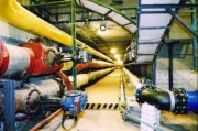
"Everything from gas pipes, steam pipes, water mains, to pneumatic postal service, high and low voltage cables, data cables, telecommunications cables and also special networks connecting individual companies. We have even been asked to install pipes to draw beer from restaurants."

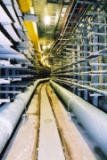
Otakar Capek says the utility tunnels or "kolektory" as they are called in Czech are a living organism which evolves constantly. In the deepest corridors, some 30-40 meters underground, a special train runs on five-kilometer routes transporting pipes, metal parts and other components. The tunnel is never complete; it is a never-ending process, says Otakar Capek and adds that this system, which he is so proud of, was mostly built during a historical period that tends to be looked down upon - the socialist era.

"Even in those days when there was a group of people who believed in something, who thought they were working on something meaningful, they could make it happen. The construction indeed had flaws of the socialist era. For example, after 1989 we had to renovate everything that did not meet safety standards. Such as fire doors made of cardboard, weak ventilators and so on."

Photo: www.kolektory.cz The Prague utility tunnels are looking forward to welcoming more tourists thanks to this new coordinated project, which is opening Prague's technological heritage to the public. And director Otakar Capek says there is more to see than wires and vaults.

"Prague is a tectonically stable area but the geology is very complex. You can find gravel sands here, clay, slate, etc., and all that poses many problems. When we were digging the big tunnel between the Municipal House and the bottom of Wenceslas Square, we basically followed the route of a 13th century ditch. It was full of objects discarded there and remnants of the old city walls which were later demolished. We worked with archaeologists and many of the objects that we found are on display right there in the tunnel."

Individual companies in Prague are now joining the venture which hopes to boost incoming tourism in the capital. When can visitors see the newly opened technological monuments? Jan Hauser of the Prague Chamber of Commerce.

"This would obviously be a question for the owners and the people who are running these sites but we hope that this summer, meaning the summer of 2007, should be the time when the first doors are opened."

From:http://new.radio.cz/en/article/87856

Tuesday, August 18, 2009

Utility Tunnel Alternatives

Note: In my last post I mentioned some of information included in this post but I had a plan to ask you a question with addressing these information, so stay with me.
Some advantages of utility tunnels are:

• Reduced road digging costs that involve traffic, road restoration difficulties and safety hazards.
• Reduced maintenance costs
• Reduced energy losses
• Utilization of public ground
• Better use of resources
• Knowledge about the utilities
• Monitoring and control
• Lower material and pipeline costs
• Encourage mid and long-range thinking
• Improved public safety
and perhaps more ....
but we know that this method have it's difficulties which are:
• Initial costs
• Coordination of authorities
• Complex design
• Tunnel management
• Security
I'm investigeting ot find new alternative methods for utility accommodation and transportation.
some conventional methods like Trenching & Joint Trenching are somehow possible to be alternative for utility tunnel.I know that Underground Utility Tunnels are an alternative and progressive measure that solves the problems that exist in the conventional method,but I want to ask you a question:
Is there any alternative for utility tunnels which can reduce digging and has lower initial costs?

The First International Conference on: Underground Multi-System Utility Tunnels


The conference will aim to cover a wide range of topics, while learning from their worldwide use, including town planning, transportation planning, various aspects of engineering, economic issues, organizational and judicial issues.

GENERAL
Town planners and sociologists see the "city" as a "service center" for the population. In the wide scope of services supplied by the city, those supplied through pipelines or ducts over and under the ground stand out in their importance. Conventionally, each utility is laid in the ground or on it usually within the statutory boundaries of the street or even under the road or pavement themselves. Underground Multi-System Utility Tunnels are an alternative and progressive measure that solves the problems that exist in the conventional method.

DEFINITION
A Multi-System Utility Tunnel (MUT) is an underground construction that serves several utilities, being a carrier of various materials, energy and data channels, through pipelines and cables that are designed and activated together. The tunnel includes service corridors that enable access, installation, monitoring, control, maintenance and connectivity to other sites.

POSSIBLE TUNNEL CAPACITY
• Water
• Sewage
• Rainwater drains
• Electric power (low voltage, high voltage, extra high voltage)
• Communications (several types)
• Street lighting
• Traffic control
• Pneumatic systems (home garbage disposals etc.)
• Fuel (and its various products)
• Hazardous material
• Gas

ADVANTAGES OF MUTs
• Reduced road digging costs that involve traffic, road restoration difficulties and safety hazards.
• Reduced maintenance costs
• Reduced energy losses
• Utilization of public ground
• Better use of resources
• Knowledge about the utilities
• Monitoring and control
• Lower material and pipeline costs
• Encourage mid and long-range thinking
• Improved public safety

DIFFICULTIES OF USAGE OF MUTs
• Initial costs
• Coordination of authorities
• Complex design
• Tunnel management
• Security

REASONS TO COMMENCE THE USE OF MUTs
Several reasons have led to the increasing of MUTs:

• Never stopping interference to traffic and its safety during repeated digging in city streets and no need to restore the original road quality.

• The immense growth in energy consumption (electric power, water), communications (telephone, cable TV and other lines), sanitation (sewage, drains and garbage disposal) in the big cities.

• Considerable reduction of available public ground, preventing conventional utility laying and density in the roads which would need more space than is available.

• A rise in public demand for quality of life and environment, the need for underground burial of power and telephone lines, addition of parking spaces, demand for green areas etc.
• Lack of control and monitoring of existing systems and difficulty in making repairs and improvements.

• Fear of terrorist damage to main and national utilities.

ALL THESE HAVE LED TO A WIDE-SCALE INTERNATIONAL RECOGNITION THAT THE
OPTIMUM SOLUTION IS THE USAGE OF UNDERGROUND MULTI-SYSTEM UTILITY TUNNELS.

SECONDARY SUBJECTS REGARDING MUTs
• Monitoring and control technology
• Maintenance
• Judicial aspects
• Financial aspects
• Safety

STUDY FIELDS
Dimensions and loads, life length, safety factors, construction methods (use of pre and pipeline materials, facing serious influences of earthquakes, influence of war and terrorism, pipeline utility joints, sealing, entrances and exits of the tunnels, sensoring, monitoring and control, tunnel service systems and internal handling and moving of equipment, implications in city planning, street layout, use of open grounds etc.

Friday, August 14, 2009

HVAC & UTILITY TUNNEL, Utah, USA


Located in Utah this project involved waterproofing a building where the foundation formed the exterior perimeter of a tunnel system that provided air return to a number of HVAC systems throughout the building. These tunnels were originally formed by casting a concrete trough; the perimeter being the building foundation with the floor and interior wall being separate components. The exterior perimeter foundation wall was waterproofed only on the inside by application of a tar-like coating. The finished foundational tunnels were approximately 2 feet tall and 3 feet wide and extended up to 175 feet. Water intrusions were present in several areas with standing water present. The contract involved cleaning, waterproofing and protecting the tunnel components from further water intrusion and water damage.
To start the actual repair process, steps were first taken to clean loose debris and then a cryogenic blasting was used to remove the previous bituminous coating and rust on the existing metal ceiling deck.

Once all non-concrete surfaces were treated, the concrete walls and floors were waterproofed with Penetron via spray application and all penetrations and non-moving joints packed with Penecrete Mortar.
This project proved a particular challenge because of the confined spaces, pumping distances and limited access. Not withstanding all of this, the tunnels are now waterproof. said Loran Hubbard of Lindhart Technical Services We were able to complete the project at a nice profit significantly under the next highest bidder. We applaud your fine product.

Source of this post:
http://www.penetron.com/newsletter/apr06/penetron_apr06.htm

Tuesday, August 4, 2009

Pardis Technology Park & It’s Utility Tunnel (Iran's CS)

There is a utility tunnel in Pardis Technology Park, which is located in north-east of Tehran
(exact location of PTP 35°44′11″N 51°48′08″E).

This utility tunnel accommodates utility networks such as clean water, waste water and gas pipes and electric , telecommunication and fiber optic cables.The length of this tunnel is 3 km.

I have collected some pictures of this utility tunnel below:

Image

Image

Image

Image

Image

Image

More information about Park's profile:

Introduction
Pardis Technology Park is located in Pardis area in the northeast of the capital city of Tehran at a distance of 20 km, with a panoramic view of Damavand Mountain, occupying a territory of 38 hectares.

Pardis Technology Park (PTP) was established in 2001, on government initiative, by Technology Cooperation Office (TCO) of I.R of Iran Presidency. The mission is to create an environment for researchers, educators and Companies with similar requirements and goals, in order to develop high-tech industries and to increase employments. PTP is run by board of directors whose members are designated by TCO and Sharif University of Technology. The management is focused on creating optimum conditions for business partners including domestic and international investors.

Mission

To encourage and support the technological companies to increase their ability to compete in international world market.

Objectives:

  1. To intensify High-tech industries development.
  2. To promote Cooperation between industries academic institutions and research centers.
  3. To create synergy between private and state sectors.
  4. To commercialize know-how and innovations generated by research centers.
  5. To promote research and development activities in private sector.


Structure:

  • Private Research & development Center
  • Incubator Center
  • Multi-tenant Building
  • Laboratories
  • Business Center
  • Administration

Services:
The Services below are planned to be established in near future:

  • Information & Communication technology Services
  • Training and education
  • Consulting, investing and marketing
  • Banking, financing and insurance
  • Laboratory and workshop
  • Exhibition
  • Housing and recreation
  • Public welfare and environmental protection

Activities:

  • Electronics and Information Technology
  • Mechanics and Automation
  • Chemistry and Biotechnology

Even more?
Pardis Technology Park
like to have a virtual tour to Pardis Technology Park?

Please leave your comments to help me improve this weblog.

Friday, July 31, 2009

The Public Utility Tunnel Mahlerlaan, Amsterdam A new Approach to the Use of Urban Underground Space

Here is a case study of utility tunnel construction project in Netherlands. this article is written by:F.M. Taselaar MA, Director/owner Hompe en Taselaar
A more efficient use of space in densely-populated areas and the desire for a high-quality city environment requires an innovative approach to accommodate the rapidly-increasing amount of cables and pipelines for public utility networks in the city. The Public Utility Tunnel Mahlerlaan in Amsterdam is one such approach. The design, construction and commissioning of the tunnel will be discussed.


Download Paper:

The Public Utility Tunnel Mahlerlaan, Amsterdam A new Approach to the Use of Urban Underground Space

Download Presentation:

Saturday, July 25, 2009

Common Utility Tunnels in Iran

I have collected some information about common utility tunnel in my country (Iran) and all over the world; however I’m sure there are more utility tunnels that is constructed around the world. There are several common utility tunnels in Taiwan, Malaysia, Netherlands, USA, Japan, and Australia that I have found in the internet. Although I have not found more countries that use common utility tunnel or at least I could not find them in the internet. Also unfortunately there is no website that contains statistics or information of world’s utility tunnels.

Below you can see a table that contains a little information about Common Utility Tunnels in Iran. I collect this information from official websites.

NO.

Common Utility Tunnels in Iran

Status

Length

Dimension

1

Amirolmomenin Boulevard , Mashhad

Constructed

1.2 km

3m width × 2m height

2

Azadegan Express way, Tehran

Under construction

5.24 km

-

3

Locale 22, Tehran

Stopped

5 km

-

4

Oroumieh

Not constructed, just act is passed

-

-

5

Pardis Technology Park, Tehran

Constructed

3 km

-

6

Imam Khomeini International Airport, Tehran

Constructed

4.8 km

4m width×3m height

7

Cultural Center of Islamic Republic of Iran,Tehran

Constructed

400 m

3.1m width×2.5m height

8

Central Bank of Iran, Tehran

Constructed

200 m

4.2m width×3.5m height

9

Mosalla-ye Imam Khomeini, Tehran

Constructed

330 m

2.5m width

10

Baharestan New town, Isfahan

Constructed

-

-

11

Tunnels of Local Electric Company, Tehran

Constructed

-

-

Now, I want to ask a question. Do you have information about Common Utility Tunnel in your country?

In my next post I will write more about Common Utility Tunnel (CUT) of those countries that I named in this post. Please comment on this blog or send whatever you know about common utility tunnel to my email address.

Wednesday, July 8, 2009

What is Utility Tunnel

The structure built above the earth and underground containing more than two sorts of public utilities, and its facilities including drainage, ventilation, lighting, communication, electricity, and relevant systems of surveillance and detection.

Traditional setting and maintenance

Setting and maintenance in Common Duct

A utility tunnel is a subterranean space for wires, conduits, pipes, and other conveyances used in the delivery of utilities with enough room for a human to enter.
A common utility duct, sometimes called a common utility conduit, is any structure – above, on, or below ground – that carries more than two types of public utility lines. However, the phrase often refers specifically to underground tunnels.


A picture of an utility tunnel taken by an urban explorer in Toronto Canada. Note the steam and electrical conduit.

Utility tunnel in the center of Zurich, Switzerland

Attention please:
utility tunnel=utility duct=utility corridor=utilidor

see also:
Utility_tunnel

Thursday, July 2, 2009

Introduction

The main purpose of this blog is to gather useful information and experiences about Utility Tunnel, (UT).

If you have any more information (such as pictures, articles WebPages and etc) in this field please send it to me.

swbd23phzm